 |
|||
|
|
|||
|
Page Title:
Bleeding Air From the Hydraulic System |
|
||
| ||||||||||
|
|
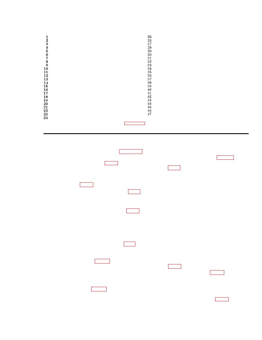
 Flared tube elbow
Axial piston pump
Reservoir shutoff valve-to-manifold tubing
Pump mount
Flared tube elbow
Shaft coupling
Pressure selector valve-to-pump tubing
Pump-to-low pressure filter hose assembly
Flared tube elbow
Pump-to-manifold tubing
Outlet selector valve-to-outlet tubing, in.
Low pressure filter-to-bleed valve tubing
Outlet selector valve-to-outlet tubing, in.
Bleed valve
High pressure relief valve-to-snubber valve tubing
Pump-to-high pressure filter hose assembly
Flared tube tee
High pressure filter assembly
Flared tube tee
Flared tube tee
Damper valve-to-snubber valve tubing
High pressure filter-to-relief valve tubing
Snubber valve-to-gage top tubing
High pressure relief valve-to-manifold tubing
Fluid pressure gage-to-dampener hose assembly
High pressure filter-to-outlet selector valve tubing
Relief valve-to-bypass valve tubing
Suction tubing
Flared tube tee
Coupling half, 1 in.
Pressure selector valve-to-bypass valve tubing
Dust protective cap, 1 in.
Flared tube tee
Flow control valve-to-outlet tubing
Pressure selector valve-to-gage tubing
Dust protective cap, in.
Flared tube elbow
Flow control valve-to-outlet tubing
Pressure selector valve-to-gage hose assembly
Dust protective cap
Bypass valve-to-reservoir shutoff valve tubing
Outlet selector valve-to-reservoir tubing
Reservoir-to-shutoff valve tubing
Relief valve-to-reservoir tubing
Filter and manifold assembly
Relief valve
Tee
Figure 12--Continued.
a. Inspecting Low Pressure Filters.
9.
(1) Start the test stand (par. 41) and
adjust the fluid volume control (29,
air to escape from the low pressure filter. Close
the valve when air bubbles no longer appear.
(2) Set the pressure selector valve (8) at
FILTER INLET position and note the
c. Connect the inch hose assembly to the
reading on the filter pressure gage
coupling half (7, fig. 2).
(6).
(3) Set the pressure selector valve (8) at
in the inch outlet position.
FILTER OUTLET position and note
e. Open the flow control valve (20).
the reading on the filter pressure gage
(6).
Remove the coupling half from the opposite end
(4) The difference between the readings
of the attached inch hose assembly and insert
(2) and (3) above, represents the
the open end into the reservoir being careful
pressure drop across the low pressure
not to damage the screen in the filler neck of
filter. Replace the filter element, b
the reservoir.
below, should the pressure drop be 20
psi or greater.
2 gpm as registered on the fluid flow indicator
b. Low Pressure Filter Element Replace-
(15).
ment.
(1) Close the reservoir shutoff valve (12,
late hydraulic fluid through the system and
back into the reservoir until all traces of air
(2) Remove plug (28, fig. 13) from the
bubbles are gone from the fluid flowing into the
bottom cover (26) and drain the hy-
reservoir.
draulic fluid from the low pressure
filter.
(3) Disconnect the low-pressure filter-to-
nect the hose assembly. Cap both ends of the
bleed valve tubing (6, fig. 12) and the
hose assembly and the coupling half of the test
pump-to-low pressure filter hose as-
stand.
23
AGO 5742A
|
|
Privacy Statement - Press Release - Copyright Information. - Contact Us |