
TM 5-2350-378-23&P
0012
FRONT CORNER (LEFT OR RIGHT) RAISES IN SPRUNG, BUT NOT UNSPRUNG MODE - Continued
NOTE
This test is performed at No. 1 front actuator which will not raise.
b.
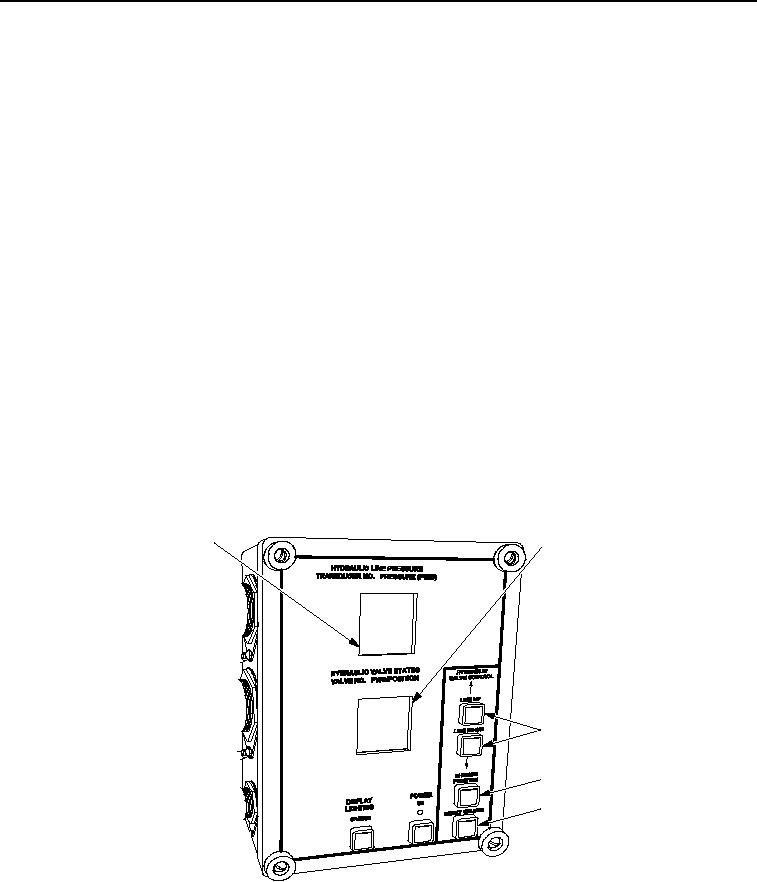
To test RIGHT No. 1 front actuator that will not rise: Using LINE UP or LINE DOWN button
(Figure 11, Item 3) on HDC control box, select V2 on HDC display (Figure 11, Item 2).
c.
Using CHANGE POSITION button (Figure 11, Item 4), close V2 on HDC display (Figure 11, Item 2).
d.
Start engine and move SPRUNG/UNSPRUNG lever to UNSPRUNG.
e.
Read transducer T-11 hydraulic pressure on HDC display (Figure 11, Item 1).
f.
Using LINE UP or LINE DOWN button (Figure 11, Item 3) on HDC control box, select V2 on HDC display
(Figure 11, Item 2).
g.
Using CHANGE POSITION button (Figure 11, Item 4), open V2 on HDC display (Figure 11, Item 2).
h.
To test LEFT No. 1 front actuator that will not rise: Using LINE UP or LINE DOWN button
(Figure 11, Item 3) on HDC control box, select V3 on HDC display (Figure 11, Item 2)
i.
Using CHANGE POSITION button (Figure 11, Item 4), close V3 on HDC display (Figure 11, Item 2).
j.
Move SPRUNG/UNSPRUNG lever to UNSPRUNG.
k.
Read transducer T-10 hydraulic pressure on HDC display (Figure 11, Item 1).
l.
Using LINE UP or LINE DOWN button (Figure 11, Item 3) on HDC control box, select V3 on HDC display
(Figure 11, Item 2).
m.
Using CHANGE POSITION button (Figure 11, Item 4), open V3 on HDC display (Figure 11, Item 2).
1
2
3
4
5
T00116HDC
Figure 11. Hydraulic Diagnostic Center (HDC) Control Box.
n.
Stop engine; relieve hydraulic pressure.
03/15/2011Rel(1.8)root(tswp)wpno(T00010)