TM 5-2350-378-23&P
0029
INSTALLATION
1.
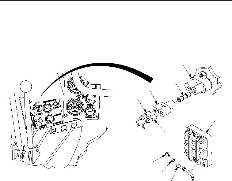
Install in-line connector (Figure 2, Item 8), "Y"-connector (Figure 2, Item 7), and lead assemblies
(Figure 2, Item 6) on trailer receptacle and trouble light circuit breaker (Figure 2, Item 1) located behind
operator's compartment switch and gauge panel.
2.
Install lead assembly 1070 (Figure 2, Item 3) on terminal B2 on parking brake relay (Figure 2, Item 2) with new
lockwasher (Figure 2, Item 4) and screw (Figure 2, Item 5).
1
8
7
6
2
6
5
4
3
M0008HDC
Figure 2.
Hydraulic Diagnostic Center (HDC) Power Distribution Components Installation.
END OF TASK
FOLLOW-ON MAINTENANCE
Connect negative battery cables (TM 5-2350-262-20).
END OF TASK
END OF WORK PACKAGE
0029-3/4 blank
03/15/2011Rel(1.8)root(maintwp)wpno(M00017)

