
TM 5-2350-378-23&P
0010
EJECTOR CREEPS - Continued
CONDITION/INDICATION
Can circuit 21 ejector relief valve be set to develop hydraulic pressure between 1,950-2,050 psi
(13,445-14,135 kPa)?
DECISION
YES - Go to Step (8).
NO - Remove all test equipment and connect hoses. Replace DCV bank (TM 5-2350-262-20).
STEP
8.
Perform ejector cylinder internal leakage test.
a.
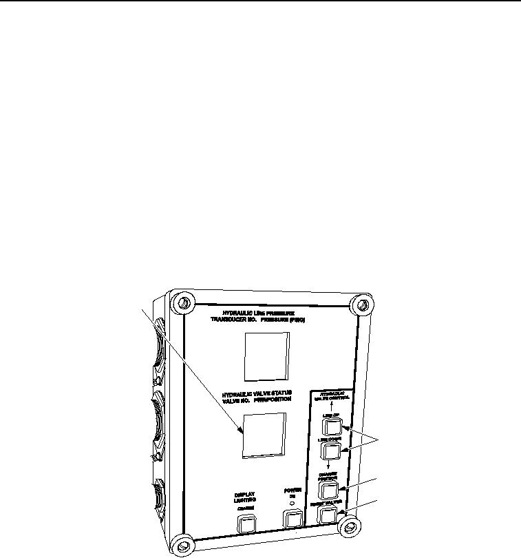
Reset all HDC solenoid valves by selecting RESET VALVES button (Figure 10, Item 4) on HDC control
box.
b.
Using LINE UP or LINE DOWN button (Figure 10, Item 2), select V1 on HDC display (Figure 10, Item 1).
c.
Close V1 on HDC display (Figure 10, Item 1), by selecting CHANGE POSITION button
(Figure 10, Item 3) on HDC control box.
1
2
3
4
T00812HDC
Figure 10. Hydraulic Diagnostic Center (HDC) Control Box.
d.
Start engine and have assistant hold EJECTOR CONTROL lever in BACK position for one minute.
e.
Mark position of ejector at side of hull and continue to hold lever in BACK position for one more minute.
f.
Check position of ejector while still holding lever in BACK position.
g.
If ejector has moved forward (extends) more than 0.5 in. (13 mm), ejector cylinder is leaking excessively.
h.
If ejector has moved backwards (retracts) more than 0.5 in. (13 mm), solenoid valve V1 on primary
manifold is leaking.
03/15/2011Rel(1.8)root(tswp)wpno(T00008)